Vacuum Pump Inlet Trap For Heavy Contaminant Vacuum Processes
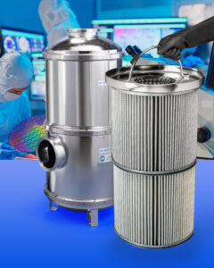
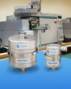
A high-capacity vacuum pump inlet trap designed to remove high quantities of contaminants from LPCVD, PECVD, MOCVD, HVPE, ALD and similar processes has been introduced


A high-capacity vacuum pump inlet trap designed to remove high quantities of contaminants from LPCVD, PECVD, MOCVD, HVPE, ALD and similar processes has been introduced
A line of robust vacuum pump exhaust traps for use with dry scroll pumps to remove carbon soot which can damage recirculation systems has been introduced
Cleaning up an LPCVD Silicon Nitride Deposition System A typical application for a multiple-stage vacuum pump trap is a reactor that deposits silicon nitride (Si3N4)
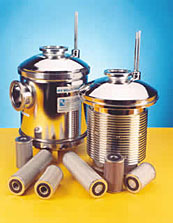
Throughput Increases in Silicon Dioxide Deposition Systems Another common application for a multiple-stage vacuum pump trap is a CVD (chemical vapor deposition) process to deposit
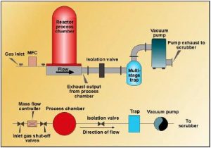
Multi-Stage Traps Clean Up Vacuum Systems Cleaning up an LPCVD Silicon Nitride Deposition System A typical application for a multiple-stage vacuum pump trap is a
Multi-Stage Traps Clean Up Vacuum By Herbert W. Gatti and Lise C.H. Laurin The costs involved in maintaining vacuum processes in a manufacturing facility can